44 civil 3d cut and fill labels
Volme grid map with cut fill labels - Civil 3D & LDD - AutoCAD Forums Civil 3D & LDD ; Volme grid map with cut fill labels Volme grid map with cut fill labels. labels; grid; fill; cut; volume; ... I am trying to create a volume grid map showing cut fill elevation differences at the grid corners and labels in each grid square stating how much cut fill is in that square. I created 2 tin surfaces, Existing Ground ... Civil Labeler - Bentley Civil Labeler. You can access this tool from the following: Drawing Production > Labels. It provides an out of the box Civil Labeler.xml file. The following configuration variable is set by default: CIVIL_LABELER_XMLFILE. You can add new Labels to this XML or create your own XML.
Solved: cut/fill surface labels - Autodesk Community This method is not really needed as this works well (just been using it today) neilyj (No connection with Autodesk other than using the products in the real world) AEC Collection 2023 UKIE (mainly Civil 3D UKIE and IW)

Civil 3d cut and fill labels
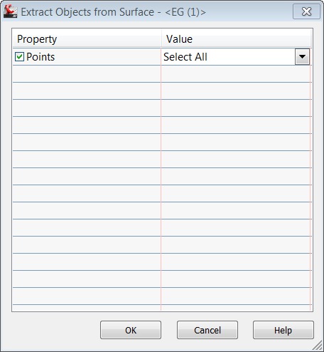
Creating Cut/Fill Volume Points or Labels in Civil 3D When you need to show cut and fill values at specific points within Autodesk AutoCAD Civil 3D, first you will need to create a volume surface. Place the desired points (or labels) which have a label style which shows the elevation, using the volume surface as the selection when prompted. To Create an Earthwork Construction Plan In the Toolspace, on the Toolboxtab, expand Civil 3D 2016 Productivity Pack 1Surfaces. Double-click Earthwork Plan Productionto display the Create Earthwork Construction Plandialog box. Select the existing ground TIN surface. Select the finished ground TIN surface. Optionally, select a grid point. Label Styles | Civil 3D 2017 | Autodesk Knowledge Network Create a Surface Spot Elevation label style named "Cut Fill." In the Label Style Composer dialog box, on the Layout tab, change the Name property of the label component to "fill." Change its color to Green. Edit the text component and change the Sign Modifier to Hide Negative Value.
Civil 3d cut and fill labels. Solved: Cut Fill Labels on Volume surface - Autodesk Community I have a problem, I need write Cut and Fill Labels on Volume surface in each 10x10 meters. Civil 3D can write Spot Levels on grid, but I need write Cut and Fill values in grid area. Using Surface >Utilities>Bounded volumes I can get the values on selected closed polygon, but write to all is very long work. Autodesk Civil 3D Tutorials Autodesk Civil 3D. The tutorial exercises are organized in a logical sequence, based on how you typically work with the different types of features. However, you may complete the exercises in any order you choose. After you begin an exercise, you should complete the steps in the order presented. Creating Cut/Fill Labels for a Volume Surfaces in Civil 3D Creating Cut/Fill Labels for a Volume Surfaces in Civil 3D - YouTube Learn how to create one Label Style to easily display the cut or fill depth in a Volume Surface by using Label Expressions.-... Cut/Fill Color Map - files.carlsonsw.com This command creates a cut/fill color map typically in red and blue in order to show the difference between grid or triangulation surfaces. In the options dialog, the ranges of the cut and fill zones are set along with the colors. The Automatic Colors has several colors styles to choose from for the cut to daylight to fill colors.
Label Styles | Civil 3D 2020 | Autodesk Knowledge Network Create a Surface Spot Elevation label style named "Cut Fill." In the Label Style Composer dialog box, on the Layout tab, change the Name property of the label component to "fill." Change its color to Green. Edit the text component and change the Sign Modifier to Hide Negative Value. Express yourself using expressions in Civil 3D - GovDesignHub 5) Create a label style that has 2 components, Cut and Fill text. These components reference the Surface Elevation, but in the text height property, you will set the corresponding expression (Cut/Fill). 6) Change the CUT component color to RED. 7) Change the FILL component to BLUE. 8) Test this out by using your new label style to label a surface!! Cut/Fill Spot Labels - AMS Workplace Technology • Change the Label type to Spot Elevation. • Change the Label Style to the one just created. • Click Add and place several labels to verify the functionality. NOTE: In Civil 3D you must have a TIN volume surface created to properly place Cut and Fill Spot Elevations. Rte 46 West, Bldg. Civil 3D Tip: Adding Section Labels to Section Views 1. Ribbon >> Home tab >> Create Design Panel >> Section Views >> Project Objects To Multiple Section Views. 2. Select a section view group. 3. The Project Objects To Multiple Section Views dialog will appear. 4. The graphic at the top represents the distance in front of the sample line and the distance behind the sample line that is to be ...
Cut Fill (3D Analyst)—ArcGIS Pro | Documentation - Esri Illustration CutFill_3d (Before_Ras, After_Ras, OutRas) When the Cut Fill operation is performed, by default, a specialized renderer is applied to the layer that highlights the locations of cut and of fill. The determinant is in the attribute table of the output raster, which considers positive volume to be where material was cut (removed), and negative volume where material was filled (added). Civil 3D Templates | ZenTek Consultants The AutoCAD Civil 3D templates that ship right out-of-the-box, just don't cut it in the real world. We need AutoCAD Civil 3D templates to be professional, concise, and easy to use, but developing the hundreds of display and label styles you need to get going is a time consuming and complex undertaking. That's where ZenTek can help! Civil 3D Label Styles: Ticks vs Blocks - IMAGINiT In the examples below two Station Labels are shown, both with two componets, Text with a 90° rotation, with a line component one as a Block and other Tick. The example below the Dragged State option is set to " Stacked Text ": Block - the line disappears, and the text is rotated. Tick - the line remains, and the text is rotated. Using Civil 3D to Create a Cut & Fill Earthwork Exhibit Once these areas have been defined, a custom spot elevation label style could be used to identify the amount of cut and fill going on in these areas. The best part is that the colorization and annotations remain dynamic to the model. Any changes made to the design will automatically be reflected in your earthwork visualization.
Creating Cut/Fill Volume Points or Labels in Civil 3D - IMAGINiT Civil Solutions Blog
Managing Cross-Section Labels in AutoCAD Civil 3D with Live ... - Autodesk Description. You've built some corridors in AutoCAD Civil 3D software. You've even created some surfaces from them. But when you get to the cross sections, you just can't get the labels right without some MTEXT or EXPLODES! This class will teach you all the tricks for creating and maintaining intelligent, dynamic cross-section labels.
About Rotating Labels in a Drawing | Civil 3D 2017 | Autodesk Knowledge Network
Making CUT/FILL Maps in AutoCAD Civil 3D | Part II | ZenTek To begin, let's create the label style we'll need for Cut/Fill mapping. Go to Toolspace > Settings> Surface > Label Styles > Spot Elevation and right-click to create a new style (below). We'll call it CUT-FILL. Next, click on the "Layout" tab and delete the default text entities there.
CAD Forum - Easier hatching between two polylines - Hatch2L.
civil4d.com » Dynamic Surface Cut-Fill Ticks! FINALLY. [Note - make sure the color and plot styles are byblock - not bylayer] Modify the label to include two blocks, plus and minus using the size of the two equations above [might want to rename them from minus scale to minus size]. Turn Off the Marker and now you have cut fill ticks, all in color.

Civil 3D_Cut & Fill Exhibit Labels Video Lecture | Study A-Z Guide ... labels and the label type i want to use is spa elevation on grid make sure that i have my cut and fill extended label option selected and just going to hit add the first surface i want to select is my finish ground this is going to reference three different objects the first one in the list is the one i want to pick so I'm just gonna go finish

Civil 3D Reminders: October 2010
Express Yourself: Using Expressions in Civil 3D - AUGI Create a label style that has two components: Cut and Fill text (see Figure 7). These components reference the Surface Elevation, but in the text height property, you will set the corresponding expression (Cut/Fill). Change the CUT component color to RED. Change the FILL component to BLUE. Figure 7
AutoCAD Civil 3D 2018 Tip: Use Civil 3D Line Label Styles to Annotate Utility Linetypes ...
Civil 3D_Cut & Fill Exhibit Labels - YouTube Civil 3D_Cut & Fill Exhibit Labels 14,133 views Feb 15, 2011 30 Dislike Share Save ProSoft 1.98K subscribers This video will take the Cut & Fill Exhibit we previously created and show you how to...

Solved: Civil 3D Labels in viewport too small. BUUUUGGG!!! - Autodesk Community
PDF CADD Users Manual - Appendix 7, dated August 2019 Civil 3D Style (Survey Figure or Point) Feature Description Feature Attributes Layer Linetype or Block Color Weight Grading Catch in Cut conditions Grading Slope Caltrans CADD Users Manual Alignment Styles Slope-Catch-Cut Line rd_SLOPE-CATCH-CUT Continuous 3 0.012 Alignment Styles Slope-Catch-Fill Catch in Fill conditions Line rd_SLOPE-CATCH-FILL

Setting up Alignment and Sample Line Labels in Civil 3d
Road design With AutoCAD Civil 3D + Open Chanel Design | Udemy Points label Lecture-3 Alignment creation tools and Settings 1. Draw alignment (no curves) 2. Draw alignment (with curves) 3. Curve settings 4. Insert pi 5. Delete pi 6. Sub-entity editors 7. Pick sub-entity 8. Points editing 9. Alignment grid view Lecture-4 Basic Alignment creation 1. Draw alignment 2. Alignment creation tools 3.

More on Civil 3D Labels (CAD Clinic: Civil 3D Tutorial) | Cadalyst
Welcome to the AutoCAD Civil 3D Tutorials - Autodesk Each tutorial set contains exercises that are designed to explore the various features of AutoCAD Civil 3D. The tutorial exercises are organized in a logical sequence, based on how you typically work with the different types of features. However, you may complete the exercises in any order you choose.

Civil 3D Reminders: LinkSlopesBetweenPoints
Surface Modeling for Infrastructure Design - Autodesk Add surface styles, labels, and tables to convey surface information on your design plans and work with volume surfaces for calculating cut and fill. Finally, wrap up the lesson by creating boundaries for surfaces. Understand surfaces and how they are used in Civil 3D. Build surfaces from project data. Edit surfaces. Use surface styles and labels.

17 Civil 3D Stuff ideas | autocad civil, civilization, autocad
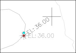
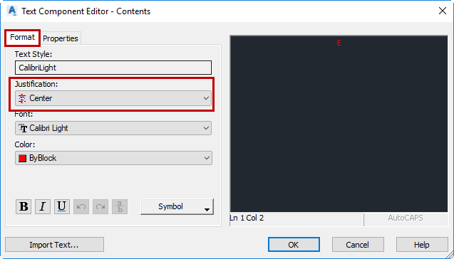
Expression Driven Cut and Fill Labels | Training Video | cadpilot Kyle demos a classic and basic Civil 3D Cut and Fill Label Style that is modified with Label Style Expressions. Yes. It is also possible to hide the chaff created in this example. This requires a Set of Expressions that work together instead of a pair and the thoughtful use of the Text Component Editor (TCE) component properties.

Cut/Fill Label in Section View - Autodesk Community
Label Styles | Civil 3D 2017 | Autodesk Knowledge Network Create a Surface Spot Elevation label style named "Cut Fill." In the Label Style Composer dialog box, on the Layout tab, change the Name property of the label component to "fill." Change its color to Green. Edit the text component and change the Sign Modifier to Hide Negative Value.

One Spot Elevation For Multi Surfaces in Civil 3D – Fingerprintvideos
To Create an Earthwork Construction Plan In the Toolspace, on the Toolboxtab, expand Civil 3D 2016 Productivity Pack 1Surfaces. Double-click Earthwork Plan Productionto display the Create Earthwork Construction Plandialog box. Select the existing ground TIN surface. Select the finished ground TIN surface. Optionally, select a grid point.
Exported Civil 3D Drawing Labels do not display at elevation | Civil 3D | Autodesk Knowledge Network
Creating Cut/Fill Volume Points or Labels in Civil 3D When you need to show cut and fill values at specific points within Autodesk AutoCAD Civil 3D, first you will need to create a volume surface. Place the desired points (or labels) which have a label style which shows the elevation, using the volume surface as the selection when prompted.

Civil 3D Labels with Multileaders - Autodesk Community

More on Civil 3D Labels (CAD Clinic: Civil 3D Tutorial) | Cadalyst

Express Yourself: Using Expressions in Civil 3D

How to create new label styles for surface in civil 3D - YouTube
Post a Comment for "44 civil 3d cut and fill labels"